|
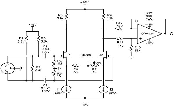
Dynamic Microphone PreampMany dynamic microphone preamps use front-ends with bipolar transistors because of the stringent low-noise performance needed. However, some listeners prefer the sound of JFETs. Softer overload characteristics and better immunity to electromagnetic interference are also among the advantages of JFETs. The microphone preamp here meets the low-noise requirement while enjoying the advantages of the JFET. The requirements for a dynamic microphone preamp include low input voltage noise and a wide range of variable gain. A typical dynamic microphone might produce 2mV at 94dB SPL (1 Pascal, Pa). The microphone preamp must accept a balanced input and have a very large controllable gain range. Simple JFET preamp The front-end can be implemented as a differential amplifier without negative feedback, as shown in Figure 1. This provides a true high-impedance balanced input with soft overload characteristics. The input stage consists of a degenerated differential a pair implemented with the LSK389 ultra low-noise dual monolithic JFET. Each JFET has a current source connected to the source. The gain is set by a variable resistance connected from source to source. Drain load resistors create a differential output that is fed to an op amp configured as a differential amplifier. In the simple design of Figure 1 the relatively low transconductance of the JFETs limits the amount of gain that can be obtained. The gain range of this simple design is limited, and not well distributed with pot rotation, even when a pot with a log taper is used. Figure 1 also illustrates the input interface where phantom power is applied by the pair of 6.8k resistors connected to +48V. Phantom power is required for condenser microphones to power their built-in preamplifier and provide a polarizing voltage for the condenser microphone capsule. Resistor R1 across the hot and cold balanced lines establishes an overall differential input impedance of about 1.7k. The very high input impedance made possible by the JFETs allows the use of relatively small-value film coupling capacitors C1 and C2 at the input, avoiding the use of electrolytic capacitors. These capacitors must be rated at 63V or more in order to handle the phantom supply voltage. This is an additional incentive to avoid the use of electrolytic capacitors. The high gain involved can prove problematic for a DC-coupled design, so a large-value electrolytic capacitor is usually placed in series with R6 in the gain-adjust circuit to bring the gain down to a very low value at DC, eliminating the offset problem. However, the electrolytic must have a very high value, on the order of 470µF, in order to preserve low-frequency response at high gain settings. Many also object to the sound quality degradation that can accompany the use of an electrolytic in a critical portion of the signal path. Here instead is used a DC servo to control output offset voltage. Details of the DC servo are not shown, but the design techniques can be found in [1].
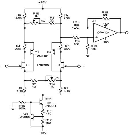
Practical design An improved design is shown in Figure 2. Each JFET is configured as a complementary feedback pair (CFP) by adding a PNP transistor in the drain circuit. This arrangement increases the effective transconductance of the JFET by a factor of about 50 and provides local distortion-reducing feedback. The JFETs are biased at 1mA and the BJTs are also biased at 1mA. Care should be taken to minimize the amount of noise from the tail current source. Here a single current source sinks 4mA through a pair of source resistors. Noise from the current source is thus in the common mode, so it is largely canceled in the differential drain circuit. Additional resistance in the emitter circuit of the feedback current source reduces its noise.
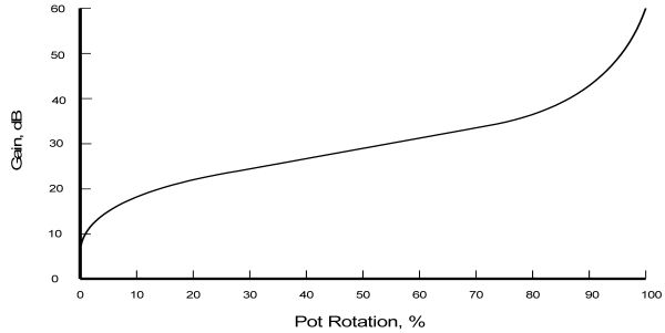
Gain control over a wide range is difficult to achieve with a single variable resistance in the JFET source circuit, so a second pot ganged with the first is added in a differential shunt arrangement in the drain circuit. A gain adjustment range of 6-60dB is achieved with a single knob, and is reasonably distributed with respect to pot rotation even when using linear pots. Gain as a function of pot rotation is shown in Figure 3. The use of log-taper pots can provide an even more uniform distribution of attenuation vs. rotation.
Noise Input noise of the preamplifier is only 1.5nV/√Hz at the highest gain setting of 60dB. At a gain of 40dB, input noise is 2.5nV/√Hz. A very quiet dynamic microphone-preamp combination has an equivalent input noise level of less than 20dB SPL, A-weighted (dB-A). This is 74dB below the reference level of 94dB. A typical dynamic microphone will produce 2mV at 94dB SPL (1 Pascal, Pa). At 40dB gain, the noise of this preamp is 2.5nV/√Hz, corresponding to A-weighted input noise of 285nV. The resistance of the microphone itself ultimately limits its self-noise level. The Johnson noise of the typical 300Ω resistance of a dynamic microphone is about 2.2nV/√Hz. The A-weighted noise of this source is 249nV. This is 78dB below 2mV and the 94dB reference level, resulting in a microphone self-noise of about 16dB-A SPL. The noise can’t get lower than this even with perfect electronics. The combination of the noise from the microphone resistance and the preamp at 40dB gain adds to 378nV. This is 74dB below the reference level of 94dB, and so corresponds to 20dB-A SPL. Dynamic range Dynamic microphones can handle extremely high sound pressure levels, limited only by the diaphragm hitting a physical barrier [3]. This is in contrast to many condenser microphones whose internal preamp electronics may clip. The maximum SPL from a human voice measured by Shure is 135dB at one inch from the mouth, while a very loud kick drum may exceed 140dB. A close-mic’d trumpet can produce even higher SPL [3]. The Shure SM58 can handle 150dB SPL at 100Hz, where it can produce a remarkable output level of 1V. While being able to handle very small sounds with low noise, the dynamic microphone preamp may be called upon to deal with very large signals like these. This often requires the insertion of an attenuating pad of 20dB in the input circuit. However, the preamp here can handle up to 1V rms without an input pad when it is set to its lowest gain of 6dB. Distortion Harmonic distortion is less than 0.002% at an output level of 1V rms for a gain setting of 20dB and rises to 0.003% at a typical gain setting of 40dB. At a gain setting of 60dB and 1V rms output, distortion is only 0.02%. Distortion is below 0.05% at 5V rms output for gain settings greater than 20dB. Distortion above the 3rd harmonic is virtually absent. The discrete input stage consumes only 4mA in this design. Significantly lower distortion can be achieved by increasing input stage current to 8 mA in a revised design. Then, for example, at 5V rms output for gain settings of greater than 20dB, THD will be less than 0.02%. 1. Bob Cordell, Designing Audio Power Amplifiers, McGraw-Hill 2010. |