|
The VinylTrak™ Phono Preamp
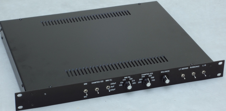
1. Introduction The VinylTrak™ phono preamp is a high-performance preamp for moving magnet (MM) and moving coil (MC) cartridges that is described in Volume 4 of Linear Audio [1]. The design includes an optional implementation of RIAA equalization that dispenses with the conventional R-C cartridge loading adjustments and the high-frequency electrical resonance with which they are associated. The complete VinylTrak™ preamp is described in depth in Volume 4 of Linear Audio (www.linearaudio.net), September 2012. The material presented here is intended to be supplementary to the VinylTrak™ preamp article. That article should be read first, as it contains most of the technical details of the design. Moving magnet phono cartridges are less expensive and more convenient than MC cartridges, but their performance is limited by their high-frequency response and high-frequency resonance. The VinylTrak™ preamp includes a different approach to achieving the 75us high-frequency RIAA roll-off that eliminates the cartridge electrical resonance and extends the electrical HF response well into the ultrasonic range. The conventional R and C cartridge loading elements are replaced by a single adjustable cartridge damping resistance for matching the preamp to the cartridge inductance. The preamp also includes conventional RIAA equalization for MM cartridges. The vastly different impedances of MM and MC cartridges make approaches with shared input amplifiers sub-optimal. The MM and MC preamps in the VinylTrak™ are entirely separate. This allows each function to be optimized for its application. The MM and MC preamps both use JFET double folded cascode differential input amplifiers with no negative feedback. The input amplifiers are DC-coupled to the cartridge. A diamond buffer completes the input amplifier. Distortion without feedback is very low due to the small signal levels. High-frequency overload margin is very good because the 75us RIAA time constant is implemented as a shunt load inside the first stage. Overload is soft due to the use of JFETs and the absence of negative feedback in the first stage. The JFET inputs provide much higher EMI immunity than do bipolar designs. The MM input amplifier uses a Linear Integrated Systems LS844 dual JFET and achieves 5 nV/rt Hz input noise. The JFET inputs virtually eliminate cartridge interaction. The MC input amplifier uses four Linear Integrated Systems LSK389 dual JFETs and achieves 0.75 nV/rt Hz input noise. This is very good for a differential JFET input. A special circuit approach is used to allow the paralleling of JFET differential pairs without introducing high-frequency instability. Both preamps are DC-coupled and include a DC servo for control of offset. There are no electrolytic capacitors anywhere in the signal path. Output functionality includes a balance control to compensate for cartridge channel mismatch, a switched low-frequency left-right signal merge to attenuate vertical flutter, a switched third order Butterworth subsonic filter and balanced outputs. An L-R signal can be sent to the outputs to aid balance control adjustment using a mono track or a center-channel voice. The L-R output mode may also be useful in setting anti-skate. 2. VinylTrak™ preamp features:
3. Design update: Transistor change Many of the small-signal transistors have been changed from 2N5551/2N5401 to 2N5089/2N5087. It was discovered that the original transistors were responsible for some of the preamp noise, primarily due to their base input noise current. This change improved the preamp S/N for both the MM and MC circuits. In the MM input amplifier these included Q5 through Q14. In the MC preamp these included Q23-Q26 and Q28-Q33. 4. Design update: Current mirror change The Wilson current mirror used in the input amplifier VAS circuits was replaced with a conventional three-transistor helpered current mirror. This change appeared to improve noise in the MM and MC circuits. The revised current mirrors are shown in Figure 1.
5. Control circuit Space did not permit showing the schematic for the control circuit in the Linear Audio article. The control circuit is primarily responsible for power-on mute and fast power-off mute to prevent any thumps from getting to the output of the DC-coupled preamp. This circuit also monitors the outputs for DC and mutes the output in the event of DC at the outputs that would result from a circuit fault. This circuit also shorts the MM cartridge inputs during mute. The circuit is shown in Figure 2. U1 and U2 are quad comparators with open-collector outputs. U1 is arranged to pull its paralleled output down if a DC voltage greater than 50mV of either polarity is detected at the hot side of the preamplifier output. R1 and C1 provide a low-pass filtering function to prevent full-amplitude audio signals down to about 10Hz from falsely triggering a DC output indication. Diodes D1 and D2 protect the polarized electrolytic capacitor C1. As will be seen in a moment, when the output from U1 is pulled low, a mute is initiated. U2 performs the power-on mute function. When power is applied, R10 must charge C5 to +10V from a discharged starting voltage of -15V. This takes about 5 seconds and allows time for the DC servos to fully stabilize. If DC is detected at the output by U1, the pull-down of U1 will prevent C5 from being charged. Once the voltage on C5 reaches +10V, U2B will pull its output low and energize the series-connected relay coils. These are 4.5V relays. Current-limiting resistors at both ends of the relay string protect U2B and the +15V supply in the event of a short. A fast power-off mute is implemented by Q1 and U2A. At power-on, C3 is quickly charged through D5 to about 19.3V. The 20V power supply voltage prior to the power supply regulator drops fairly quickly when power is interrupted. C3 holds the emitter of Q1 at 19.3V while the voltage at Q1's base falls with the raw power supply voltage. This turns on Q1 before the power supply regulators fall out of regulation. That in turn quickly charges C4 from -15V to the -10V threshold of U2A. This in turn causes U2A to pull down its output, discharge C5 and initiate a mute. C4 reduces the tendency for the power-off circuit to activate if a very brief drop in the mains occurs due to another piece of equipment being turned on. Relays K5 and K6 ground the hot and cold outputs of both channels when they are not energized. Relay K1, located on the MM preamp board, grounds the MM cartridge inputs when it is not energized. It serves to protect the DC coupled cartridge from current that would flow in the unlikely event that an input JFET gate would become shorted to its source or drain in a fault condition.
6. Power supply The power supply was also not shown in the LA article. The power supply consists of a main power supply and numerous local active capacitance multiplier filters. The main supply provides ±16V from LM317/337 regulators. The BJT capacitance multipliers drop a bit more than a Vbe, bringing the rail voltages on the boards down to about ±15V. The schematic for the main power supply is shown in Figure 3. It is quite conventional, employing a small toroidal power transformer and using high-speed rectifiers in its bridge. The supply includes generous amounts of reservoir capacitance in a pi-filter arrangement ahead of the 3-terminal regulators. The complete preamplifier draws about 200mA from this supply. The mains input includes a safety ground breaker circuit to mitigate system ground loops. The ground is broken by R7, a 10-ohm resistor. In the event of a fault, the large bridge rectifier will prevent the line safety ground and the circuit ground from ever differing by more than one diode drop.
Every signal-path circuit block in the preamp is powered from a secondary point-of-load active capacitance multiplier filter. A total of 20 of these filters is used. These filters not only further attenuate the noise on the ±16V rails, but they also re-reference the rail voltage to the local signal ground. The schematic for the active capacitance multipliers is shown in Figure 4. These are simple emitter followers whose base is connected to a heavily-filtered version of the input rail (R1 and C2). The emitter follower pass transistor operates at a collector-base voltage equal to the small drop across R1 that results from Q1's base current. This is a fairly small voltage drop, as the individual circuits fed by these capacitance multipliers consume fairly small amounts of current. Overall, each capacitance multiplier drops less than 1V, resulting in rail voltages of about ±15V for the circuitry being powered. Diodes D1-D4 protect the pass transistors in the event of a fault. The capacitance multipliers provide 37dB of attenuation at 120Hz, increasing to over 60dB of attenuation from 2kHz to beyond 100MHz.
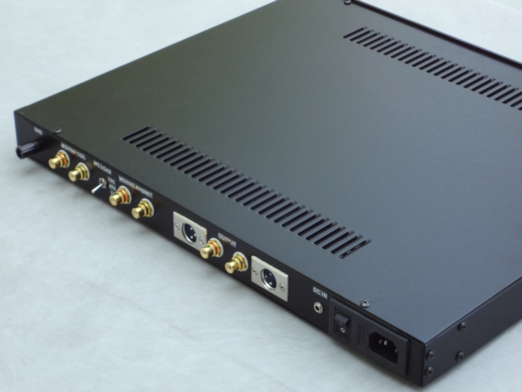
The VinylTrak™ preamplifier can be powered from an external ±20V dongle power supply instead of its internal mains-powered supply. This approach keeps the mains and its associated hum and noise out of the box. Some view the powering of line-level audiophile components by wall transformers with disdain. How could such an inexpensive solution provide a high quality power supply worthy of use in high-end equipment? Well, think again. The current requirements for such line-level equipment are relatively low, and allowing only clean DC into the equipment enclosure has great hum, noise and EMI advantages. The class 2 wall transformer also allows one to dispense with the mains power supply safety ground, eliminating ground loops. The VinylTrak™ preamplifier requires only 8 watts at the ±20V DC input. The regulated DC supplied by the dongle power supply is re-regulated down to ±16V by the preamp's internal regulators shown above in Figure 3. The external DC is simply wired to the outputs of the main bridge rectifier. The schematic for the external dongle power supply is shown in Figure 5. A fairly hefty 20V AC, 500mA wall transformer feeds two half-wave rectifiers to create approximately ±24V (under load) to feed LM317/337 3-terminal regulators that produce regulated ±20V rails for use by the preamplifier. Generous amounts of reservoir capacitance in a pi-filter arrangement are needed to deal efficiently with the half-wave-rectified raw DC. The need to employ half-wave rectification with AC wall transformers is one of the challenges with the wall transformer powering approach. By their nature wall transformers are poorly regulated, so the rectified voltage may rise quite high under no-load conditions. For this reason the reservoir capacitors should be rated at 50V or more.
7. RIAA accuracy and Inverse RIAA network The equalization frequency response was tested with a Lipshitz inverse RIAA network [2], shown in Figure 6. An audio oscillator with an output of several hundred millivolts is connected to the input of the inverse RIAA network and the output of the network is connected to the MM RCA input jack. The overall frequency response to the output of the preamplifier should then be flat. It is very important to first verify as a reference that the combination of the oscillator feeding the AC voltmeter directly is flat. Accuracy of the VinylTrak™ preamp was within ±0.1dB without any extraordinary measures in achieving precision in the passive components. However, the polystyrene capacitors used in the preamp EQ were hand-selected using a capacitance meter because they were not specified as ±1% tolerance.
The effect of component tolerances on RIAA EQ accuracy is important in selecting tolerances for the critical passive components involved in the RIAA equalization. A simplified schematic of the VinylTrak™ RIAA equalizer is shown below in Figure 7. R1 and C1 implement the 75us time constant while R2-R4 and C2 implement the low-frequency portion of the EQ. We note that 0.1dB corresponds roughly to 1%. The passive-active equalizer topology used here isolates the high-frequency and low-frequency equalizer portions, eliminating some interactions and simplifying the effects of component tolerances. A 1% error in R1 or C1 creates an EQ error that is small in the mid-band and gradually increases to 0.086dB at 20kHz. A 1% error in R2 causes a gain error of about 0.07dB that is flat to within 0.01dB. A 1% error in R3 creates an EQ error that is small in the mid-band and gradually increases to 0.074dB at 20kHz. A 1% error in R4 creates an EQ error that is small in the mid-band and increases to 0.065dB at 20Hz. A 1% error in C2 creates an EQ error that is small at 20Hz and in the mid-band and rises to its maximum of 0.07dB at 150Hz. Although accurate RIAA equalization is important, it should be kept in perspective in regard to the much larger frequency response errors in the loudspeakers. Perhaps more important is the RIAA equalization matching between the channels. A channel-channel frequency response mismatch might detract from imaging.
8. Quasi-differential input Figure 8 shows the input interface from the single-ended RCA plugs. Because the MM and MC input amplifiers inherently have a true high-impedance symmetrical differential input, we can get some advantage from that even when a single-ended RCA plug is employed. This is done by connecting the differential inputs across the terminals of the floating RCA connector and connecting the normally-ground terminal of the RCA connector to signal ground through a 10-ohm resistor. This can help break ground loops. It goes without saying that the input stage lends itself perfectly to balanced XLR phono inputs, but turntables with balanced XLR interconnects are rare.
9. Noise performance Updated noise measurements for the MM and MC circuits are summarized below, both A-weighted and un-weighted in a 20kHz bandwidth. The reference level for the MM preamp is 5mV input while that for the MC preamp is 500uV. Inputs are shorted.
These numbers compare very favorably with other phono preamps. The noise performance of the MC preamp is of special interest because JFETs were used in its front-end implementation. 10. Real-world noise with moving magnet cartridge connected Phono preamps are not operated with their inputs shorted in the real world; they are connected to a cartridge that presents substantial impedance in the case of moving magnet cartridges (830 ohms in series with 370mH for a Shure V15 Type V). Because of its inductive component, this impedance can rise to tens of kilohms at high frequencies. As a result, the cartridge loading resistance, nominally 47k, can contribute a significant amount of Johnson noise at the input. Simulations indicate that even with a perfectly noiseless preamp, the achievable A-weighted signal-to-noise ratio with a Shure V15 Type V cartridge is about 82.5dB as a result of this effect. The estimated system S/N of this preamp connected with that cartridge is about 80.5dB. The real-world noise penalty of the MM preamp in damped mode with a cartridge connected was mis-stated in the LA article. This was kindly pointed out by Marcel van de Gevel [3]. The damped mode of RIAA equalization available in the VinylTrak™ preamp for MM cartridges employs a smaller value of cartridge loading resistance, and this can lead to a larger overall Johnson noise contribution. This penalty is about 2.5dB as compared to the conventional form of equalization with a 47k load. This number is for a Shure V15 Type V cartridge, and is somewhat dependent on the particular cartridge coil resistance and inductance. A small part of the penalty also arises from the fact that the noise of the input amplifier is not attenuated as much at frequencies above 8kHz by the 75us portion of the RIAA EQ. The estimated S/N for the damped mode using a Shure V15 Type V cartridge is 78dB. It is notable that the S/N for MM preamps under shorted-input conditions is almost always better than that for comparable active MC preamps, often by about 5dB. However, under real-world conditions with an MM cartridge attached, the smaller MM preamp S/N becomes comparable to that of the MC preamp (even in the case of the VinylTrak™ damped EQ mode). One must also bear in mind that the MC cartridge is not a short circuit. A typical MC cartridge with a 10-ohm coil will generate 0.4 nV/rt Hz of Johnson noise. This will degrade an 80dB A-weighted MC preamp S/N by about 1.5dB down to 78.5dB. 11. Synthesized cartridge loading The Johnson noise of the conventional 47k cartridge loading resistor can create a noise current that results in additional preamplifier noise. This effect can be reduced by synthesizing the 47k resistance with negative feedback. If an inverted signal with a gain of 10 is made available, a feedback resistor of 517k connected to that point in the circuit will create an effective load of 47k while injecting less Johnson noise. This is an old idea. One implementation can be found in [4]. Unfortunately, I was in error in explaining the potential noise advantage of the synthetic cartridge loading approach in the LA article, as once again kindly pointed out by Marcel van de Gevel [3]. When properly implemented, the noise advantage of synthetic cartridge loading can be significant. The two simple circuits shown below in Figure 9 illustrate how synthetic cartridge loading works. In a nutshell, shunt feedback is used to create smaller impedance with a higher resistance. In (a), the preamplifier employs a flat-gain input stage with a gain of 10 (20dB). This boosts the signal out of the noise floor for the following circuits and provides a very high impedance input for the MM cartridge. The signal voltage across RL' is easily seen to be 11 times that of the input signal. To cause the same signal current to flow as with a real 47k resistor, RL must be 11 times the 47k value, or 517k. From a noise point of view, however, the much higher resistance of the 517k resistor injects much less noise current than did the real 47k resistor. Thus arises the noise advantage. The approach in (a) is what I employed in a phono preamp that I designed circa 1980. In many preamplifiers the input amplifier includes some or all of the RIAA equalization. This spoils the functioning of the simple circuit in (a). The VinylTrak™ preamplifier is an example of a preamplifier with some EQ in the first stage. In such cases the circuit in (b) can be used. U3 simply creates a replica of the necessary signal that would have been created had U1 been a flat amplifier. Such an approach has been employed in [4]. The effectiveness of synthetic loading in the real world is best evaluated with simulation. It is important to recognize that a fundamental source of noise is the winding resistance of the MM cartridge itself. The 830-ohm winding resistance of the Shure V15 Type V creates an input noise level of about 3.6 nV/rt Hz even in the absence of a cartridge load resistance and any amplifier noise. The promise of reduced noise by load synthesis brings with it some extra complexity and the opportunity to lose the noise advantage in some implementations. This is especially the case in the circuit of (b) where an extra amplifier is connected to the sensitive cartridge input node. If BJT op amps are used for the input amplifier and replica amplifiers in (b), simulations show that their added input current noise may negate most of the noise advantage promised by synthetic loading. JFET-input amplifiers are best used in these locations because of their absence of input current noise.
One might also ask if voltage noise in U2 and U3 adds significant noise to the final result, detracting from the noise advantage of the load synthesis circuit. Simulations show that this has very little effect in most designs where the noise of these amplifiers is not large compared to that of the input amplifier. For example, there is negligible degradation if the input amplifier has input noise of 5 nV/rt Hz and the two feedback amplifiers have input noise of 8 nV/rt Hz. In fact, even if the noise of U2 and U3 is 12 nV/rt Hz, the reduction in noise advantage is only about 0.5dB. This is good news because it means that JFET op amps can be used for U2 and U3 without compromising the noise advantage. Although not used in the VinylTrak™ preamplifier, the load synthesis technique can prove valuable when applied to it. Simulations show that it improves the S/N of the damped mode by 2.4dB to the point where it is virtually the same as that of a conventional EQ approach with a real 47k load. Two things appear to be responsible for this. First, the 196k load synthesis feedback resistor eliminates the noise penalty imposed by the smaller 18k load resistance in the damped approach. Secondly, since the 196k resistor is still substantially larger than the real 47k resistor in the conventional EQ case, the extra noise benefit tends to offset the remaining noise penalty of the damped approach due to the 8kHz zero placed in the 75us part of the RIAA EQ. As an interesting aside, this arrangement allows the cartridge load resistance to be adjusted by changing the gain of the load synthesis feedback amplifier at a lower-impedance, less sensitive point in the circuit. This is feasible as long as the gain needed to achieve the lowest desired load resistance does not cause a potential input overload vulnerability in the load synthesis feedback amplifier. If need be, a smaller load synthesis feedback resistor of 100k or 150k could be used to mitigate this concern without giving up too much S/N. There may also be a tendency for cartridges with a lower inductance, which need a smaller load resistance in the damped approach, to have smaller output amplitude. 12. Noise weighting It is notable that the ubiquitous A weighted noise measurement is not entirely the most appropriate for measuring noise, especially in phono preamps where the noise spectrum is highly non-uniform due to the RIAA equalization curve. The A weighting noise measurement specification is very old, and is based on the audibility of single tones at different frequencies. It is related to the Fletcher-Munson equal-loudness contour at a sound level of 40 phon. The A-weighting curve is not generally representative of the audibility of random noise as a function of frequency. Nevertheless, the A-weighting curve is largely the de-facto standard for specifying signal-to-noise ratio in audio equipment and in other areas. In order to better reflect the audibility of random noise as a function of frequency, the ITU-R 468 weighting curve was developed. Compared to A-weighting, this curve reflects more sharply-falling audibility of random noise at frequencies above 6kHz. Beyond 6kHz, audibility falls at more than 24dB/octave, with peak sensitivity occurring at 6kHz. Below 6kHz, audibility falls at 6 dB/octave. The A weighting curve and the ITU-R 468 curve have equal reference audibility at 1kHz and 15kHz. At 6kHz, the ITU-R 468 audibility is about 12dB higher than that for A weighting. Figure 10 shows the A-weighting and ITU-R 468 weighting curves together. The peak in the ITU-R 468 curve at 6kHz is quite notable, as is its steep roll-off at higher frequencies.
Although A-weighted and ITU-R 468-weighted signal-to-noise ratios cannot be directly compared, it is notable that for a white noise source, the ITU-R 468 measurement will yield +2.7dB more noise, corresponding to a lower S/N. The difference between A-weighted noise measurements and ITU-R 468 noise measurements demonstrates that two preamplifiers with the same A-weighted noise performance may likely have different amounts of perceived noise if their noise spectral distribution is different. Moreover, these curves bear on the audibility of noise and do not necessarily reflect on the psychoacoustic effect on perceived audio quality. In other words, apart from audibility, different noise spectra may be subjectively more or less annoying to the listening experience. 13. Distortion Distortion is of special interest because of the use of un-degenerated JFET input stages with no negative feedback. As explained in the article, the no-feedback input amplifiers permit the use of the transconductance-shunt R-C implementation of the RIAA 75us time constant. They also eliminate the need for a low-impedance feedback network to preserve low-noise performance. Finally, they permit having a true high-impedance balanced input that can be useful in eliminating ground noise even when conventional single-ended RCA turntable inputs are used. Distortion is quite low, largely as a result of the small signal amplitudes present at the inputs of the MM and MC amplifiers. Total Harmonic Distortion (THD) at 1kHz and 20kHz versus input level for the MM preamp is shown in Figure 11 below. The gain at 1kHz was set to 35dB. Notice that distortion rises gradually with increased input amplitude, as expected for an un-degenerated JFET input stage. Of special interest is the THD at the +20dB overload point (50mV rms), which is only 0.016%. These measurements were conducted with the preamplifier set for 35dB of gain at 1kHz. Notice that the distortion at 1kHz and 20kHz is not very different. This is expected, since the distortion over much of the range is determined by the un-degenerated JFET input pair. THD-1 at the nominal 5mV MM input level is only 0.0011%. At the 20-dB overload point of 50mV it is still only 0.016%. Notice how the distortion rises gradually. This is an indication that the distortion is soft and well-behaved. At this point, the harmonic structure is almost all third, as to be expected from an un-degenerated JFET differential pair. There are no higher harmonics of any significance at all. THD-1 is still only 0.09% at a full 120mV input. Overload occurs at the onset of op amp output clipping at 172mV input, where THD-1 is still only 0.2%. 20-kHz THD for the MM preamp is only 0.01% at 50mV input and its measurement extends to higher input levels because the lower equalized preamp gain at 20kHz keeps the op amp output stage from clipping as early. THD-20 does not reach 1.0% until a very large input level of 500mV rms is applied. In fact, a 20kHz sine wave remains quite sinusoidal and exhibits very soft clipping behavior up to a whopping 900mV input.
The robustness to high-frequency overload is due in large part to the use of the transconductance-shunt R-C approach for implementing the RIAA 75us time constant in the first stage, which keeps the high-frequency voltage swings low right from the beginning of the signal chain. Distortion for the MC preamp is shown in Figure 12 below. In this case the gain is set to 55dB. As in the case of the MM preamp, the maximum input level at 1kHz is limited by clipping of the output op amp at about 10V rms. THD-1 is only 0.001% at an input level of 2.5mV. THD-1 at a nominal input level of 500uV is un-measurable. At a 20-dB overload level of 5mV above 500uV, THD-1 is still only 0.003%. Just under output clipping, at an input level of 17mV, THD-1 is only 0.03%. As with the MM preamp, THD-20 in the MC preamp is similar to that at 1kHz because distortion in the un-degenerated JFET input pair dominates. As before, 20kHz performance extends to higher input voltage levels because output stage clipping does not occur until much higher input levels as a result of the lower gain at 20kHz. At an input level of 10mV, 26dB above the 500uV nominal input reference level, THD-20 is only 0.007%. At an input level of 50mV, fully 40dB above 500uV, THD-20 is only 0.37%. Even at 100mV, THD-20 is only 3% and the MC stage is into soft clipping.
14. Overload Overload margin for the MM and MC preamps at 1kHz and 20kHz is summarized below. Overload is expressed as rms input voltage level. Overload is declared when THD reaches 1%. The input overload margin for the preamps is prodigious at 20kHz due to the transconductance-shunt R-C implementation of the RIAA 75us time constant. In the 1-kHz cases, the maximum overload margin is simply dictated by the maximum output of the output amplifier, which is about 10V rms. Gain at 1kHz for the MM and MC preamps was set to 35dB and 55dB for the overload measurements.
Real-world overload of the MM preamp when driven from a cartridge in the damped mode is even somewhat greater. This is due to the low-pass filter that is formed ahead of the input stage by the cartridge inductance and the lower-than-usual cartridge load resistance. That low-pass cut-off in the damped EQ mode begins at 8kHz. The large high-frequency input level tolerance for both the MM and MC preamps contributes to especially good EMI immunity as well. This is a direct result of the use of JFETs at the input in combination with the gm-shunt R-C 75us EQ that prevents large-amplitude high-frequency signals from propagating through the signal path. 15. JFET gain spread The input stages of the MM and MC preamps operate without negative feedback, so the gain spread due to device-to-device variations among JFETs is of interest. That is why gain trim pots were put in the signal path of the preamps. 10 different LS844 JFETs from two different batches fabricated two years apart showed a gain spread of just ±0.7dB. This is impressive, especially given that the threshold voltages of the first batch were on the order of 1.6V and those of the second batch were on the order of 0.6V. The key to this small gain spread is that differential pairs of the same type of device tend to have similar gain when they are operated at the same tail current. 16. Conclusion As mentioned above, this material is intended to be supplementary to the VinylTrak™ preamp article that appeared in Volume 4 of Linear Audio, and that article should be read first, as it contains most of the technical details of the design. 17. References 1. VinylTrak - A Full-Featured MM/MC Phono Preamp, Bob Cordell, Linear Audio, volume 4, September 2012, available at www.linearaudio.net. 2. On RIAA Equalization Networks, Stanley Lipshitz, JAES, June 1979. 3. Private communications with Marcel van de Gevel. 4. Preamplifier 2012, Douglas Self, Elektor, Part 2, May 2012.
|
|||||||||||||||||||||||||||||||||||||||||||||||||||||||||||||||||||||