|
VCA-based Faders and Panning PotsVoltage-controlled amplifiers Voltage-controlled amplifiers (VCAs) are widely used in the analog portions of mixing consoles and other pro-audio processing functions. They are especially useful in supporting automation. The Blackmer? VCA produced by dbx Inc. has long been the most widely used VCA. It has been made available in IC form by THAT Corp. since the company’s inception [1].
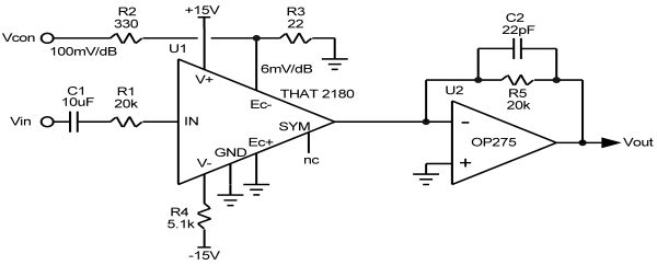
A simple VCA using the THAT 2180 chip is shown in Figure 1. The 2180 is a current-in, current-out device. R1 converts the input voltage to a current at the low-impedance input of the 2180 chip. The output signal current is fed to the virtual ground of U2 and the signal is converted to a voltage by means of feedback resistor R5. The 2180 provides decibel gain/attenuation that is linear with control voltage. In the circuit shown, the control coefficient is 100mV/dB. A fader can be implemented with a pot that merely produces a low-impedance DC voltage to control the gain of the VCA. The VCA is also available in a dual version, the 2162. The circuit shown is simplified, and the control port circuit shown can require significant current. See [1] and related application notes for better approaches to control port buffering. The 2180 and 2162 are pre-trimmed for low distortion, but they allow the use of a trimming circuit that injects a small current into the SYM pin that can be adjusted for lowest distortion. The trim circuit is not shown here, but can be found in [1]. VCA Mixers The current output nature of the 2180 makes it handy in mixers, since multiple 2180 VCAs can be arranged to drive the virtual ground of U2 in Figure 1. An additional advantage is that the noise gain of the U2 mixing circuit is not increased as channels are added to the mixer, as is the case with conventional mixing circuits. This is because the input mixing resistors are effectively replaced by signal current sources. Each output of the 2180 has about 15pF of capacitance to ground, so C2 may have to be increased a bit for stability as additional VCAs are added to the bus. Panning circuits The pan pot in a mixer distributes a channel signal to the left and right summing busses in a proportion that determines the location of the source on the sound stage. This is usually done in such a way that the power sum for that signal in the left and right channels is constant with changes in position. A source panned to the center would then be down 3dB in each channel. In reality, the loudness in the left and right channels does not always sum on a power basis, and can under some conditions be perceived to sum on more like a sound pressure level (SPL) basis, which would suggest constant-voltage panning where a centered source would be down 6dB in each channel. A frequent compromise is to have the centered source be down 4.5dB [2]. Designing pan pot circuits with a pair of potentiometers that implement the desired signal distribution law can be a challenge involving numerous compromises. Using a pair of VCAs, with their convenient linear decibel control law, can make the design easier and better-performing [3]. The THAT 2162 dual VCA is a good choice for this application. The two VCAs are driven with opposing nonlinear control voltages arranged so that the DC voltage provided by the pan pot when set for center causes the output to each channel to be down by 3.0dB for a constant-power law. The DC control voltage to each VCA can be created with nonlinear circuits to achieve the desired pan pot control law. Once again, the current output of the VCA makes it convenient to drive the virtual ground right and left summing busses directly without summing resistors that increase mixer noise gain.
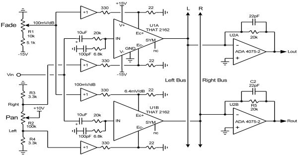
The VCA has two control inputs, one of each control polarity. They can be driven differentially or independently. The negative control port can be driven with the pan pot control signal while the positive control port can be driven by the fader signal, implementing the fader and pan pot functions together with a single dual VCA. The ability to do this while keeping the pan position the same with different fader levels is made possible by the linear decibel control law of the VCA. A simplified diagram of such a circuit is shown in Figure 2. The +1 unity gain control buffers must be able to deliver up to 27mA at –10V to drive the low-impedance VCA control port resistive divider. Once again, better approaches to buffering the control port signals can be found in [1]. The resistive dividers of the panning potentiometer and its associated resistors create nonlinear control voltages as a function of rotation that are remarkably close to what is needed to implement the constant-power panning law. Power is constant within a ±0.2dB window over the full rotation of the pan pot, with maximum attenuation of the low side approaching 100dB. The panning law can be changed to a –4.5dB compromise law merely by changing R3 and R4 to 5200Ω. 1. THAT Corporation, Blackmer? Pre-trimmed IC Voltage Controlled Amplifier, 2180 and Dual Pre-trimmed 2162 datasheets, www.thatcorp.com. 2. Douglas Self, Small Signal Audio Design, Focal Press, 2009. 3. THAT Corporation, VCAs in a Pan Potentiometer Application, Design Note 120. |